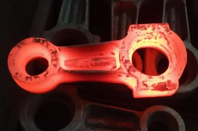
Regles de disseny per minimitzar el mecanitzat després del forjat
Machining is often necessary after forging, but it does not have to account for a large portion of the total manufacturing work. If the forging is designed with the final machined component in mind, manufacturers can place material where it is needed and avoid creating unnecessary stock that must later be removed by turning, milling, drilling, or grinding. The objective is not to eliminate machining completely. Critical dimensions, holes, bearing seats, threads, sealing surfaces, and other functional features commonly require machining to achieve the required tolerance and surface finish. The more practical objective is to make the forged blank as close as reasonably possible to the final component while leaving enough material for those operations. This approach makes the relationship between part design, die design, material flow, and machining much more important. During the early planning stage, engineers should evaluate the finished geometry, required tolerances, load conditions, material, forging temperature, and available equipment together. A well-planned procés de forja can then produce a component that requires machining only in selected areas rather than across most of its surface.
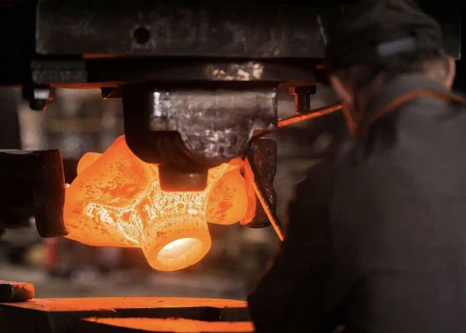
How Should the Finished Part Guide Forging Design?
Start with the final machined geometry.
A forging should not be designed independently from the finished component. The final machined geometry should be the starting point for determining where forging stock is required and where the forged surface can remain close to its final dimensions.
For example, a shaft may require accurate bearing seats at both ends, while the center section may only require a less precise diameter. It would be inefficient to provide the same machining allowance across the entire shaft. The bearing seats need sufficient stock for turning or grinding, but other areas can potentially be forged closer to their final dimensions.
The same principle applies to flanges, bosses, connecting sections, gear blanks, and other irregular components. Engineers should identify functional surfaces first and then determine which areas require additional forging stock.
This creates a more controlled transition between forging and machining. Instead of removing a large amount of material from every surface, the machining operation becomes focused on the features that actually require tight dimensional control.
Define machining allowances by feature.
A common mistake is to apply a uniform machining allowance to the entire forging. In practice, different features may require different allowances depending on their tolerance, surface condition, location, and machining method.
A surface that will be turned on a lathe may need a different allowance from a surface that will be milled or ground. Similarly, a critical sealing face may require more controlled stock than a non-functional external surface.
The allowance also needs to account for realistic forging variation. Die wear, material movement, temperature changes, trimming, heat treatment, and dimensional variation can all affect the final forging dimensions. If the allowance is too small, machining may expose defects or fail to clean up the surface completely. If it is too large, valuable material and machining time are wasted.
For this reason, machining allowance should be treated as a design parameter rather than simply an extra amount of metal added to the drawing.
How Can Material Flow Reduce Unnecessary Machining?
Design the performance around material movement.
Material flow is one of the most important factors in a near-net-shape forging. During forging, the billet does not simply shrink into the shape of the die. Material moves in different directions according to the applied load, die geometry, temperature, friction, and local resistance.
A good performance directs this movement before the final cavity is filled. This can help distribute material more evenly and reduce excessive buildup in areas that would otherwise create large amounts of flash or machining stock.
For complex forgings, a single operation may not provide sufficient control over material distribution. Upsetting, drawing, blocking, bending, or other preforming operations can be used before the final forging operation. The exact sequence depends on the component geometry and material.
The purpose is not simply to make the process longer. A properly designed preform can make the final operation more predictable and reduce the amount of excess material that must later be removed.
Protect critical sections from underfill and defects.
Reducing machining allowance does not mean reducing it blindly. If too little material reaches a critical area during forging, the resulting part may suffer from incomplete fill or other geometry-related problems.
This is why material flow must be considered together with the final machining plan. A small amount of additional stock may be justified in an area where material movement is difficult during the procés de forja, while another area may be suitable for a much tighter forged dimension.
Engineers can therefore use material flow analysis to identify locations where the forging naturally tends to accumulate or lose material. The forging geometry can then be adjusted before production rather than discovering the problem after machining begins.
Which Die Design Rules Help Reduce Post-Forging Machining?
Place the parting line strategically.
The die parting line has a direct influence on material flow, flash formation, and the geometry of the finished forging. Its location should be selected according to the shape of the component rather than simply according to the easiest die configuration.
An unsuitable parting line can create unnecessary flash or place a difficult-to-machine feature directly at the die split. It may also make trimming more complicated and introduce additional variation into the forging.
A well-positioned parting line can make the cavity easier to fill and the forging easier to trim. It can also help place flash in an area where it can be removed without affecting important functional surfaces.
This is particularly important when the goal is to minimize machining. If the parting line creates excessive material near a finished surface, the machining operation must remove that material later. A better die layout can prevent some of that work at the source.
Use appropriate draft angles.
Drafting is necessary in many impression-die forging operations because the forged part must be removed from the die cavity. However, excessive draft can add unnecessary material to the forging geometry and increase subsequent machining.
The appropriate draft depends on the forging method, material, die configuration, cavity depth, and production conditions. It should therefore be determined as part of the complete die design rather than treated as a fixed value for every component.
The design objective is to provide enough draft for reliable die release while keeping the forged geometry as close as practical to the required shape.
Use generous radii where material flow requires them.
Sharp internal corners are difficult to fill during forging and can increase local deformation requirements. They can also increase stress concentration in the die.
Properly designed fillet radii provide a smoother path for material to flow into the cavity. This can improve filling and reduce the likelihood that additional material will have to be left for machining simply to compensate for poor forging geometry.
However, increasing every radius is not automatically beneficial. The radius still needs to be compatible with the final component and the required machining operations. A radius should support both manufacturability and functional requirements.
When Is Near-Net-Shape Forging Appropriate?
Use near-net geometry selectively.
Near-net-shape forging is particularly useful when reducing machining volume is an important production objective. However, it should not be interpreted as an instruction to forge every feature to its exact final dimension.
Some features are naturally suitable for near-net forging, while others are better produced by machining. External profiles, bosses, and general contours may often be brought close to their final dimensions through forging. In contrast, precision holes, threads, bearing fits, and sealing surfaces commonly require additional machining during the procés de forja.
The best design therefore combines forging and machining rather than treating them as competing processes.
A successful near-net-shape strategy asks a simple question for every feature: Can this geometry be produced consistently by forging, or is machining the better way to achieve the required specification?
Consider dimensional variation before reducing stock.
Near-net-shape designs leave less material available for correction during machining. This makes dimensional control more important.
Before reducing machining allowance, engineers should understand the expected variation from the forging operation. Factors such as die wear, temperature, press control, material condition, and heat treatment can influence the final dimensions.
If the process variation is larger than the available machining stock, an aggressive near-net-shape design can create production problems. The correct approach is to reduce unnecessary stock only after the forging capability has been evaluated.
How Do Simulation and Process Planning Support Better Forging Design?
Simulate material flow before cutting production dies.
Finite element analysis can help engineers evaluate how material is expected to move through the forging cavity. Instead of relying entirely on trial-and-error die development, simulation can provide an early indication of potential filling problems, excessive flash, high strain areas, and other process issues.
This is particularly valuable for complicated components. A change in preform geometry or die design can be evaluated before committing to production tooling.
Simulation should not replace engineering judgment. Its value comes from combining the predicted material behavior with practical information about the press, tooling, material, and production sequence.
Evaluate temperature and deformation together.
Forging temperature affects material flow behavior, deformation resistance, die filling, and dimensional stability. The appropriate temperature range varies by alloy and forging method.
If the material becomes too resistant to deformation, filling the cavity may require excessive force. If the temperature is not properly controlled, the material may not flow consistently from one area to another.
Temperature control is therefore directly connected to machining reduction. More consistent forging conditions can produce more consistent geometry, making it easier to use a smaller and more controlled machining allowance.
Quin paper hi juga la selecció de materials?
Select alloys that match the forging geometry.
Not every alloy behaves in the same way during forging. Differences in flow stress, forgeability, thermal behavior, and deformation characteristics affect how easily a material can be formed into a particular geometry.
When a component requires a complex near-net-shape profile, material selection should therefore be considered alongside die and process design. A material that can be reliably formed within the available forging conditions may provide better dimensional consistency than one that requires more aggressive processing.
Material selection should also consider the final component requirements. Strength, toughness, wear resistance, corrosion requirements, heat treatment, service temperature, and machinability may all affect the final manufacturing route.
Account for heat treatment and dimensional change
Forging is not always the final thermal operation. Many forged components undergo normalizing, quenching and tempering, solution treatment, aging, or other heat-treatment processes before final machining.
These operations can influence dimensions and shape. If the procés de forja is designed with an extremely small machining allowance without considering subsequent thermal processing, there may not be enough stock to correct dimensional changes.
A reliable design therefore considers the complete route:
billet → preforming → forging → trimming → heat treatment → machining → inspection
Machining reduction should be evaluated across the entire sequence rather than only between forging and machining.
How Can Forging and Machining Be Designed as One Manufacturing System?
Identify which surfaces truly need machining.
The most effective strategy is often to classify surfaces according to their functional requirements.
Precision fits and sealing surfaces normally need tighter control. Threaded features generally require machining or another dedicated forming method. Non-critical external surfaces may be left closer to their forged condition if their dimensional and surface requirements allow it.
This feature-by-feature approach prevents engineers from automatically applying the same machining allowance everywhere.
Design inspection requirements at the same time
Reducing machining can change how the forging needs to be inspected. When more of the final geometry is retained directly from forging, the consistency of the forging operation becomes more important.
Dimensional inspection, visual inspection, material verification, and other applicable quality checks should therefore be considered during process planning. The inspection method should match the critical characteristics identified on the component drawing.
For suppliers producing customized forgings, this also makes communication between the customer and manufacturer essential. The supplier should understand which dimensions are functional, which surfaces will be machined, and which forged surfaces can remain in their as-forged condition.
Balance material savings against process capability.
The lowest possible machining allowance is not always the lowest-cost solution. A design that requires extremely tight forging tolerances may increase tooling complexity, process control requirements, inspection requirements, or rejection rates.
The better objective is to find the economic balance between forging precision and machining effort.
For high-volume production, investing in optimized tooling and process development may significantly reduce machining time over thousands of parts. For lower-volume customized components, a slightly larger machining allowance may sometimes be more practical than pursuing an expensive near-net-shape solution.
This is why the best forging process is not simply the one that produces the smallest forging. It is the one that provides the required final component with a reliable combination of material usage, forging capability, machining time, tooling cost, and quality control.
Conclusió
Implementing effective design rules for minimizing machining after forging requires more than simply trying to make the forged component smaller or closer to its final dimensions. The finished component should be considered first, followed by a careful evaluation of machining allowances, material flow, die geometry, preform design, material behavior, heat treatment, and process capability.
Strategically placing machining stock allows critical surfaces to receive the material they need while avoiding unnecessary stock on less demanding features. Proper parting line placement, draft angles, fillet radii, and preform operations can further improve material distribution and reduce excess flash or difficult-to-machine regions. Near-net-shape forging can provide additional savings when it is applied selectively and supported by appropriate process control.
Simulation and process analysis can also help identify material-flow and die-filling problems before production tooling is completed. At the same time, material selection and thermal processing must be considered because they can influence both forging behavior and final dimensions.
For customized components, these decisions are most effective when forging and machining are planned as one manufacturing route rather than as separate operations. A well-designed procés de forja can reduce material waste, shorten machining time, simplify production, and provide a more consistent starting point for final machining without compromising the functional requirements of the component.
Shaanxi Welong Int'l Supply Chain Mgt Co., Ltd. provides customized metal manufacturing solutions covering forging, sand casting, investment casting, centrifugal casting, and machining. Established in 2001, the company operates with ISO 9001:2015 and API-7-1 quality systems and supports components made from iron, steel, stainless steel, aluminum, copper, zinc, and various alloys. Its engineering and production capabilities allow customers to coordinate forging, machining, material selection, and quality control within a broader manufacturing program. With experience serving customers across Europe, North America, Asia, and Oceania, the company focuses on customized production and international supply chain management for industrial components. For inquiries, please contact us at metal@welongpost.com.
FAQ
1: What are the main benefits of minimizing machining after forging?
The main benefits include reduced production costs, improved efficiency, better material utilization, and enhanced product quality.
2: How does near-net-shape forging contribute to reducing machining requirements?
Near-net-shape forging produces parts closer to final dimensions, significantly reducing the amount of material that needs to be removed through machining.
3: What role do advanced simulation tools play in optimizing forging processes?
Advanced simulation tools help predict material flow, identify potential defects, and optimize die designs, reducing the need for physical prototyping and post-forging machining.
4: How does material selection impact the need for post-forging machining?
Choosing appropriate alloys with favorable forging characteristics can lead to better dimensional accuracy and surface finish, reducing machining requirements.
referències
1. Smith, JA, i Johnson, RB (2019). Tècniques avançades de forja per a la fabricació amb forma gairebé neta. Journal of Materials Processing Technology, 285, 116-128.
2. Brown, EC, i Davis, LM (2020). Optimització del disseny de matrius per minimitzar el mecanitzat postforjat. International Journal of Advanced Manufacturing Technology, 106(5), 2345-2360.
3. Wilson, PK, i Thompson, SE (2018). Estratègies de selecció de materials per millorar l'eficiència de la forja. Materials & Design, 150, 35-48.
4. Lee, HS, i Anderson, MR (2021). Aplicació de l'anàlisi de elements finits (FEA) en el disseny i l'optimització dels processos de forja. Procedia Manufacturing, 52, 68-73.
5. Garcia, CL, i Martinez, FJ (2017). Forja amb forma gairebé neta: principis i aplicacions industrials. Advanced Materials Research, 264, 1578-1583.
6. Taylor, AW, i Robinson, KL (2022). Innovacions en la tecnologia de forja per reduir els requisits de mecanitzat. Journal of Manufacturing Processes, 74, 239-254.

Share your inquiry, get the quotation accordingly!
Xina WELONG: el vostre soci de confiança en solucions metàl·liques